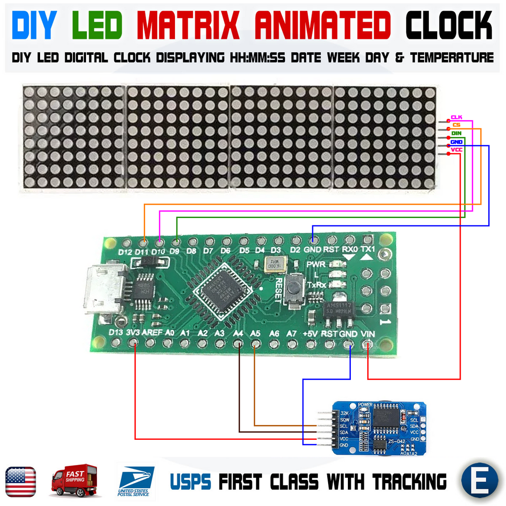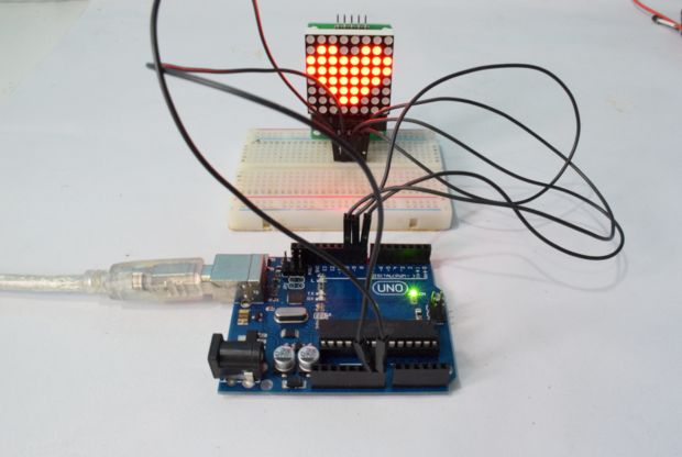

- #Arduino led matrix max7219 how to
- #Arduino led matrix max7219 driver
- #Arduino led matrix max7219 code
#Arduino led matrix max7219 driver
For example, to turn all LEDs off except one LED at row 1 and colum 1, you need to write to register 1 value 0b00000010 in binary or 0x02 in hexadecimal. LED Matrix Driver MAX7219 IC Driver Module + LED Dot Matrix 8x8 32mm x 32mm 4 Arduino LED Matrix Driver MAX7219 Arduino -> LED Matrix Driver MAX7219. By writing to these 8-bit registers, you can make individual LED on or off. Register 0 (DIGIT_0 register) controls 8 LEDs of row 0, register 1 (DIGIT_1 register) controls 8 LEDs of row number 1, and so on.


The MAX7219 has 8 registers, numbered from 0 to 7, which are used to control 8 rows of LEDs. My led display normally until i turn on 4 leds in 1 column, it turn off imediately. arduino and max7219 led matrix clock and thermometer ati hd uadio driver. I use Arduino Uno and IC Max7219 to control led matrix 8x8. These LEDs are arranged in rows and columns which are illustrated in the below figure. dot setparam (params, value None) Set parameters into the Booster. The module consists of a 8×8 LED matrix or 64 individual LEDs. MAX7219 8×8 LED Dot Matrix moduleįirst, let’s have a look at the 8×8 LED dot matrix module which is controlled by MAX7219 chip. I have tried some higher resistors to no effect.In this tutorial, you will continue learning C++ by building a C++ class for controlling 8×8 LED Dot Matrix MAX7219 using Arduino. I have a 1uF capacitor between the power and ground. The primary components for this circuit are: Arduino Mega 2560 R3 and.
#Arduino led matrix max7219 how to
A library meant for people who have little/no knowledge about Arduino to drive an LED matrix display with text with a focus on performance and simplicity. Learn how to wire the 8x8 LED display Matrix to Arduino Mega in a few simple steps. I'm using a 10k resistor between pin 16 and the power on the max7219. A library for the MAX7219 LED display drivers. You may use it to display time, date, temperature, humidity, desired text, alerts, Instagram followers, YouTube subscribers, views, animated texts, emoji, and other information with just a few taps. I have read that the max7219 cannot drive some higher-power White LEDs because of voltage requirement, but since all of the White Matrix seems to power up, I'm not sure that is the problem. In this guide, we will build a smart DIY Wi-Fi-based clock using an ESP8266 microcontroller, and MAX7219 4x8x8 LED matrix. The ingredients used are still the same as the previous article. And in this article, we will learn to make smile emoticons using this matrix display using Arduino too. I show you how to use Led matrix displays using Arduino. When I start to send data to the max7219, the next Green array driven by the second max7219 displays the appropriate image, but in the White Matrix all of the LEDs remain on, but their brightness seems to dim slightly with the data changes. In this tutorial 'Controlling a Led Matrix Using Arduino'. Here's what happens when I swap out the Green Matrix for the White Matrix on my breadboard: All of the LEDs on the White Matrix power on immediately when the power to the Arduino is turned on.
#Arduino led matrix max7219 code
Most libraries assume one way (presumably the way the library author had his in the first place) and the code is written for that configuration X. There are basically 4 logical ways that a matrix can be wired to the MAX72xx. I figured (not knowing too much about electronics) that since the pin configuration of the matrix was the same, this wouldn't require too much require too much fiddling to get the White Matrix to work. It has been explained many times before on many forums. For the project that I'm working on, I decided to switch from a Green LED matrix:


 0 kommentar(er)
